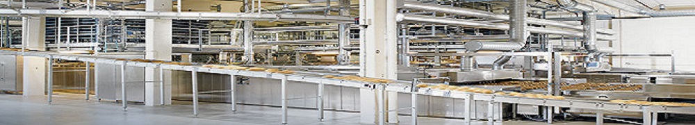

As shown in the sketch below, the production line that was mechanically jammed has an Infeed section, an Oven, a Cooling section and an Outfeed section. The width of the line is approximately 1.5 meter. It has two double pitch roller chains running at both side of the line with carriers hanging in between the two roller chains.
Both roller chains are a few hundred meters in length passing through multi loops as shown in the sketch. Thus the whole line is running with two motors (drive 1 & drive 2). There is a synchronizing encoder in between the two drives, sensing the tension condition of the chain and controlling the speed on drive 2 in related to drive 1. This serves to share the whole line load between the two motors.
The incident started with an alarm, "drive 1 mechanically overloaded". The production team reported the issue to engineering team and they started the trouble shooting process.
The engineering team first noted that there was no output from the variable frequency drive unit of motor 2. Hence they thought it was the faulty variable frequency drive that causes motor 2 not working which lead to mechanical overload alarm of drive 1. With this finding, they planned to check into the variable frequency drive unit and replace if necessary.
When I was informed on such issue, I stopped them from any work on the variable frequency drive but ask them to check into the position of synchronizing encoder. I explain to them that the variable frequency drive 2 might have no output if the synchronizing encoder indicates that the section of roller chains driven by motor 2 are tight. The check was carried out and proven right. The synchronizing encoder was fully retracted because the sections of rollers chains for "cooling" was tight.
I ask the team to check on any obvious mechanical jam, especially by the ends of all loops because a straight run of chain normally should not jam. The team finally reported thaty there was no obvious jam and they are running out of idea on how to check further.
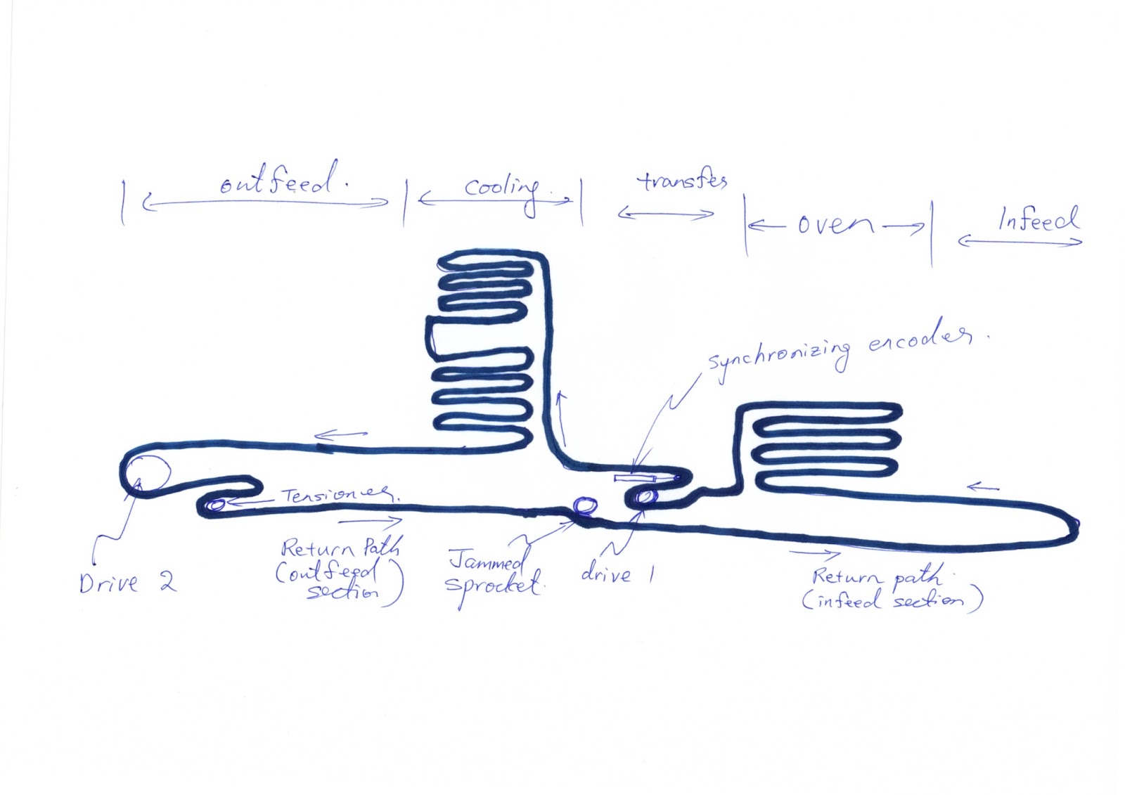
Then I decided to manually pull stretches of rollers chain in various sections of the production lines, with the intention to feel if there is any difference in tension. The tensioner on the outfeed end for both roller chains are released before the "feeling process".
The "feel" of both rollers chains (both sides of the production line) in the cooling section are quite even. The same goes to those roller chains in the oven. When it came to the infeed end, the roller chain on the left hand side seems to be tighter as compare to the right hand side. The difference became more obvious on the return path of the roller chain. The difference was very slight and I decide to get the executives, engineers and supervisors to feel the difference too as a matter of On-Job-Training.
Finally when it came to feeling the roller chains on the return path of the outfeed section, a greater difference in tension was found. With this "feel" action, we finally manage to trace toward the jammed sprocket as shown in the sketch.
Removing baking trays from the section and climbed into the suspection area, we then found the little M6 X 10 Counter sunk screw jamming in one of the sprocket.

With such a small piece of screw jamming in one of the sprocket which is not easily accessible, the tracing technique is important or else it would be difficult to find even though the problem is truely minor. Hence I decided to share it in my blog here and hope that readers who had read this will be able to lear the little practice of "feeling the machine" during trouble shooting.

